
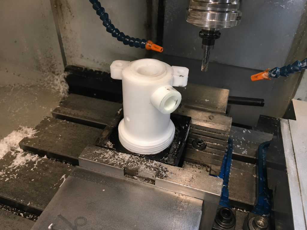
POM Spool, Piston and Body CNC Machining Case Study
Drawing-based machining of three close-fit POM components for a U.S. customer assembly, with focus on functional diameters, cross holes, external thread starts and clean deburring.
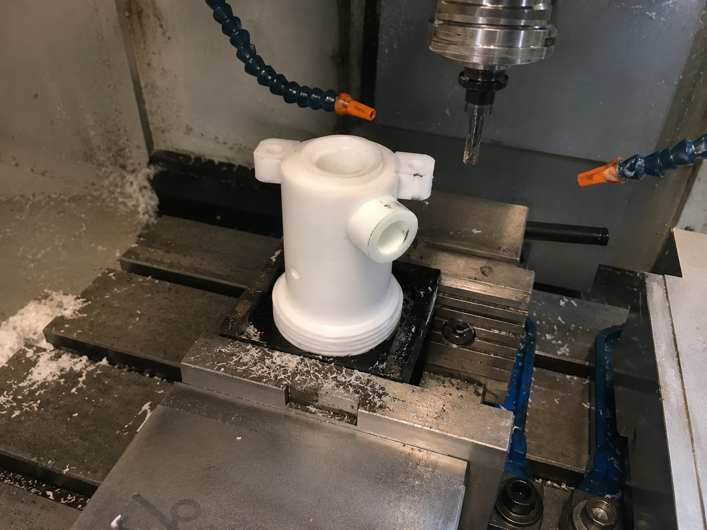
Three Functional POM Parts in One Assembly
This order came from a U.S. customer as an inch-dimensioned assembly. Several items belonged to the set, but the three parts that carried the real machining risk were the body, spool and piston. Those were the components Micrylix produced.
On paper the parts look modest: white POM, mostly turned and milled features, several bores and cross holes. In the machine shop, the difficult work was keeping the functional diameters controlled while avoiding soft burrs at holes, shoulders and thread starts.
Body, Spool and Piston
POM Body
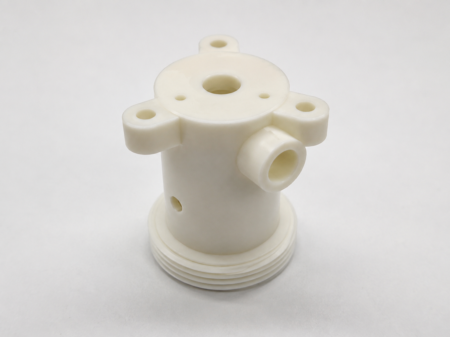
The body combined a cylindrical shell, side port, mounting ears, external thread area and several checked bores. The main risks were hole location, bore finish, thread-start cleanup and burr control around the side port.
POM Spool
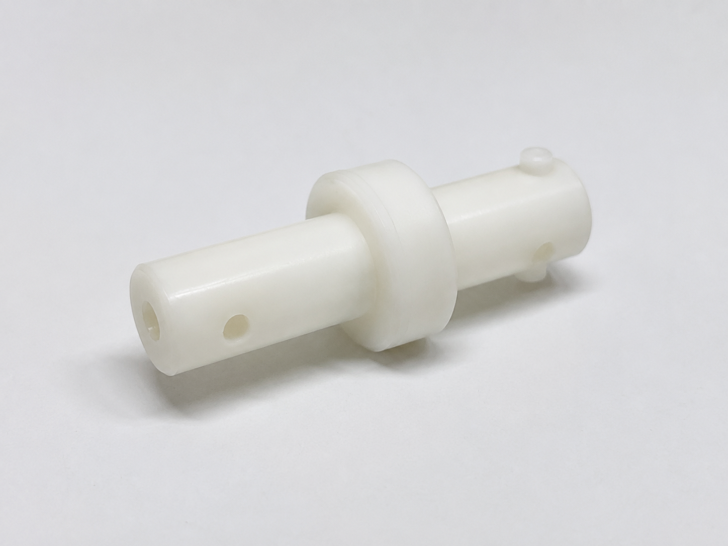
The spool required controlled shaft diameters, shoulders, cross holes and small lip details. The workholding had to support the slender body without marking the surface or pushing the part out of round.
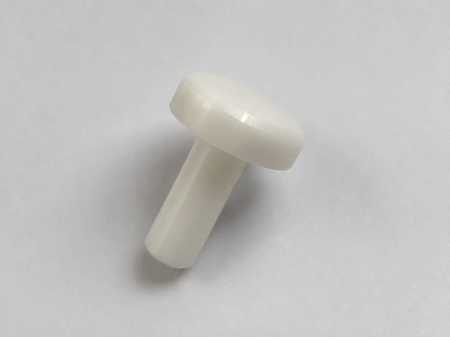
POM Piston
The piston was a simple-looking part with a small stem and larger head. The critical points were the stem diameter, shoulder transition, chamfer control and maintaining a clean sliding surface.
How We Controlled the Machining Risk
Where the Parts Could Go Wrong
| Feature | Risk | Machining Focus |
|---|---|---|
| Body bores and side port | Burrs at the port intersection and slight ovality after clamping. | Controlled clamping, finish boring strategy and manual edge review. |
| External threaded section | Thread starts can raise small lips that interfere with mating parts. | Clean thread lead-in, light deburring and thread-fit inspection. |
| Spool cross holes | Exit burrs can remain inside the diameter and affect sliding or fluid passage. | Support during drilling and careful secondary deburring. |
| Piston stem | Small diameter can deflect if cut too aggressively. | Reduced cutting load, stable support and final diameter inspection. |
Inspection Focused on Assembly Fit
The checked features were the functional diameters called out on the drawings, cross-hole openings, thread starts, shoulder locations and general surface condition. Because the drawing set used inch dimensions, inspection was kept in inch units to avoid conversion mistakes during review.
The finished body, spool and piston were cleaned, visually checked for burrs and reviewed against the drawing requirements before shipment. The final parts were supplied as a matched set for the customer’s assembly work.
Why POM Was Suitable
POM was a practical choice for these parts because it offers good machinability, low friction and stable behavior for many mechanical components. Grade selection and final fit still depend on the customer’s load, working environment and assembly requirements.
Related CNC Plastic Machining Services
For similar drawing-based projects, see POM CNC machining, custom CNC machined plastic parts, and plastic valve bodies.
Need CNC Machined POM Components?
Send your drawing, material requirement, quantity, tolerance needs and application notes. Micrylix will review machinability, workholding risk, burr control and inspection requirements before quotation.