
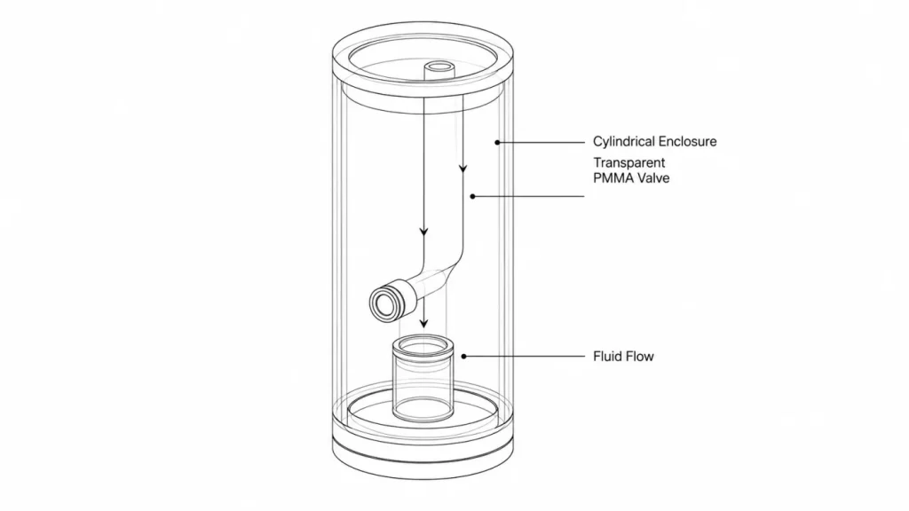
PMMA MACHINING GUIDE
Common CNC Machining Defects of Optical-Grade PMMA Transparent Valve Components
Root causes and industrial-grade preventive solutions for PMMA valve cracking, cloudiness, tolerance drift, edge chipping, internal bubbles, and sealing surface defects.
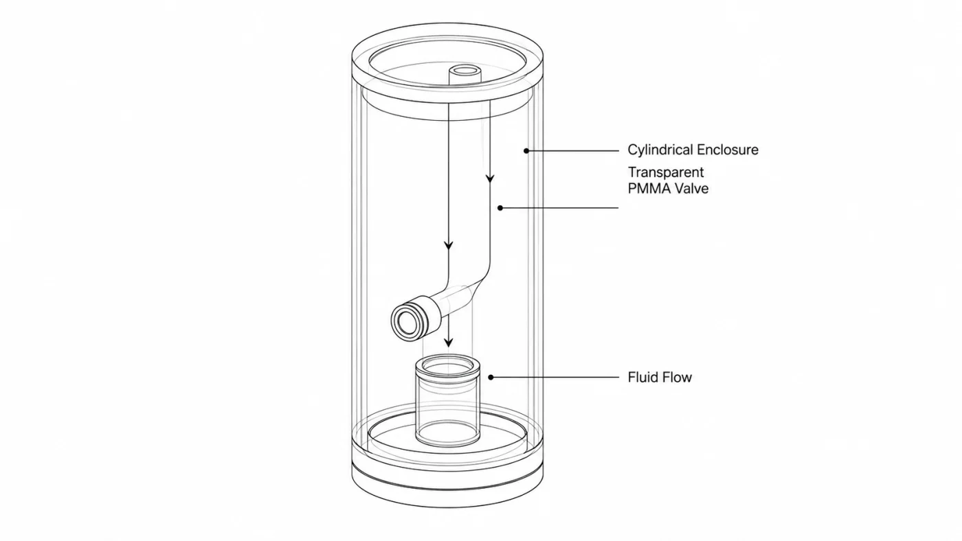
Why PMMA Valves Fail During Precision CNC Machining
Optical-grade PMMA, also known as acrylic, is widely used for transparent fluid valve assemblies in laboratory instruments, medical liquid delivery systems, microfluidic fixtures, and analytical test equipment. It offers excellent visual clarity, low weight, and good compatibility with many low-corrosion aqueous fluids.
PMMA is also heat-sensitive and stress-sensitive during subtractive machining. Improper cutting speed, tool geometry, fixturing, chip evacuation, or material conditioning can create cosmetic and functional defects: micro-crazing along flow-channel edges, cloudy haze, tolerance drift, delayed cracking, and leakage at sealing surfaces.
This article summarizes practical defect causes and process controls for custom transparent PMMA valve parts, with a focus on drawing-based CNC machining rather than molded commodity parts.
Top 6 Critical Defects in Machined PMMA Fluid Valve Parts
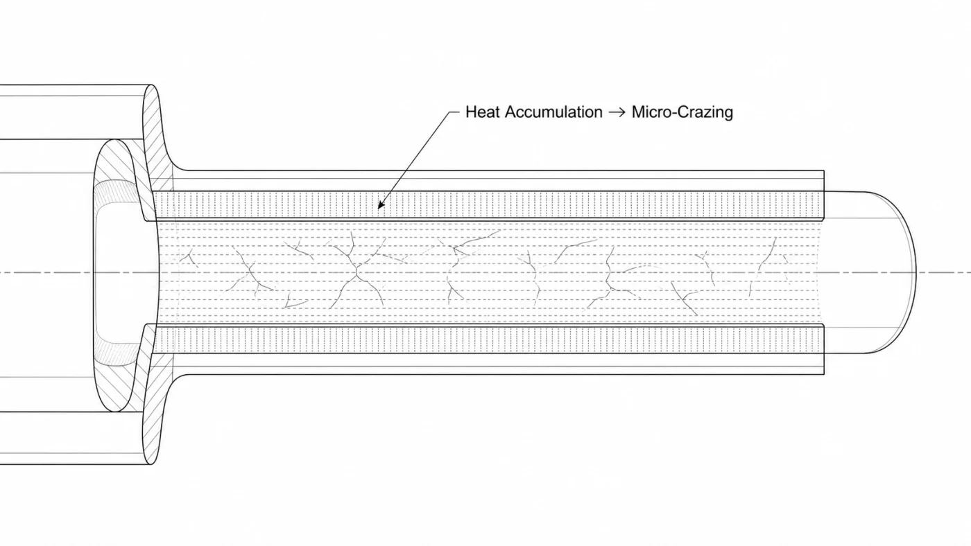
1. Cloudy White Haze and Micro-Crazing on Internal Flow Channels
Root causes: excessive spindle speed, localized melting heat, chip recutting, and insufficient dry air cooling. Narrow fluid channels trap heat, especially in thick or enclosed valve geometries.
- Use climb milling to reduce secondary chip friction.
- Reduce RPM for deep internal bore machining and tune feed rate to avoid rubbing.
- Apply continuous clean dry air at the cutting zone instead of water-based coolant inside fluid cavities.
- Use low-temperature annealing when stress-sensitive surfaces are involved.
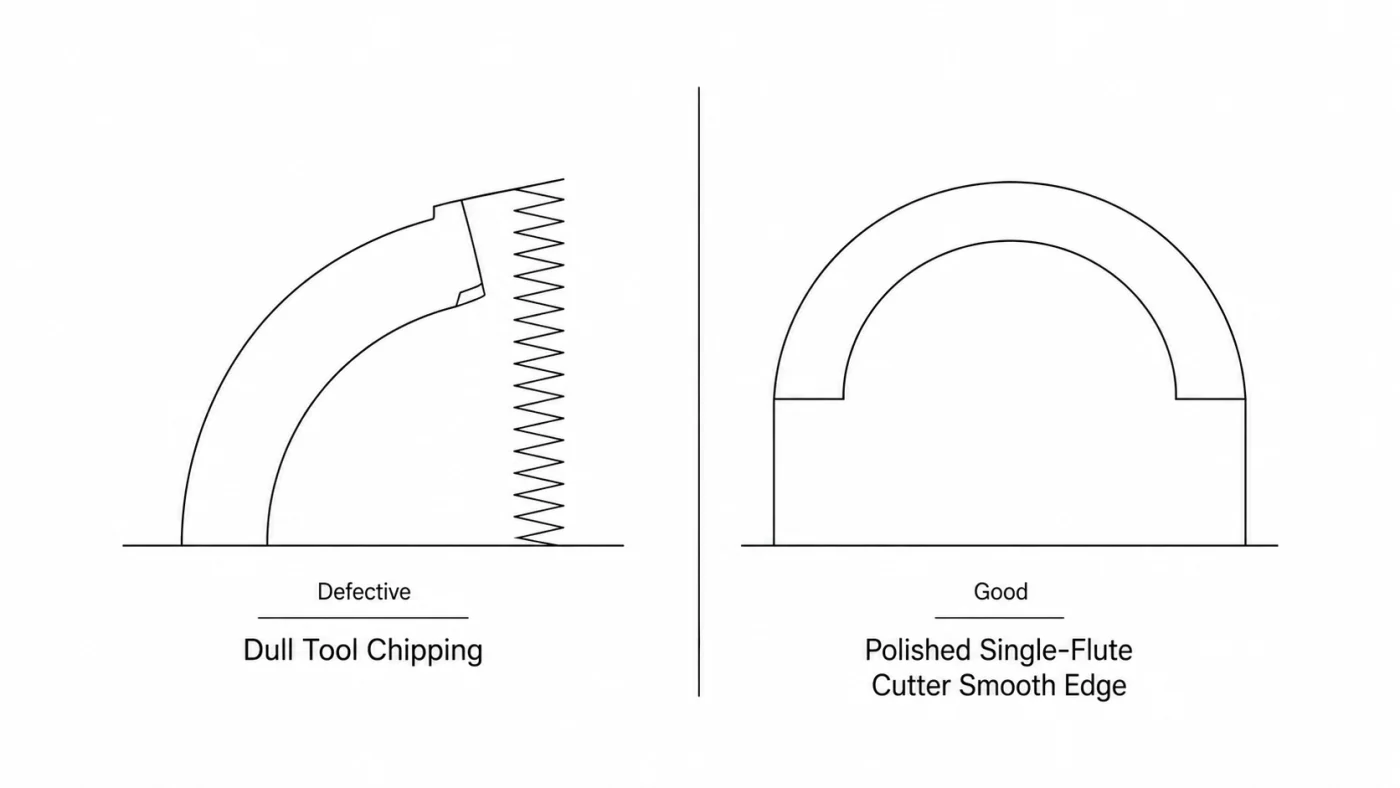
2. Edge Chipping on Valve Sealing Surfaces
Root causes: dull cutters, excessive radial engagement, unsupported thin walls, and vibration during machining. Even small chips may affect gasket compression and sealing reliability.
- Use polished single-flute carbide tools dedicated to optical plastic machining.
- Limit radial depth of cut near transparent sealing edges.
- Use full-surface fixturing or vacuum support to reduce vibration.
3. Dimensional Tolerance Drift
Root causes: thermal expansion, internal stress release, unstable workshop temperature, or thin-wall geometry movement after machining. For PMMA valve parts, practical tolerance capability depends strongly on geometry, wall thickness, and inspection method.
- Condition material before machining.
- Machine small batches under stable temperature control.
- Inspect critical bores, sealing faces, and gasket interfaces using CMM or optical measurement.
4. Hidden Internal Bubbles in Transparent Walls
Root causes: moisture retained in stored PMMA stock and heat generated during cutting. When trapped moisture vaporizes, it may form permanent internal bubbles or whitening.
5. Surface Tool Lines Reducing Optical Clarity
Root causes: vibration, uneven feed, roughing-only toolpaths, or skipping semi-finishing. Tool lines can reduce visual monitoring of liquid flow and make inspection windows harder to use.
6. Delayed Stress Cracking After Assembly
Root causes: unreleased internal stress combined with detergents, alcohol-based cleaners, high humidity, or bolt compression. Delayed cracks may appear days or weeks after assembly if stress relief is skipped.
Standardized Pre-Machining PMMA Material Treatment
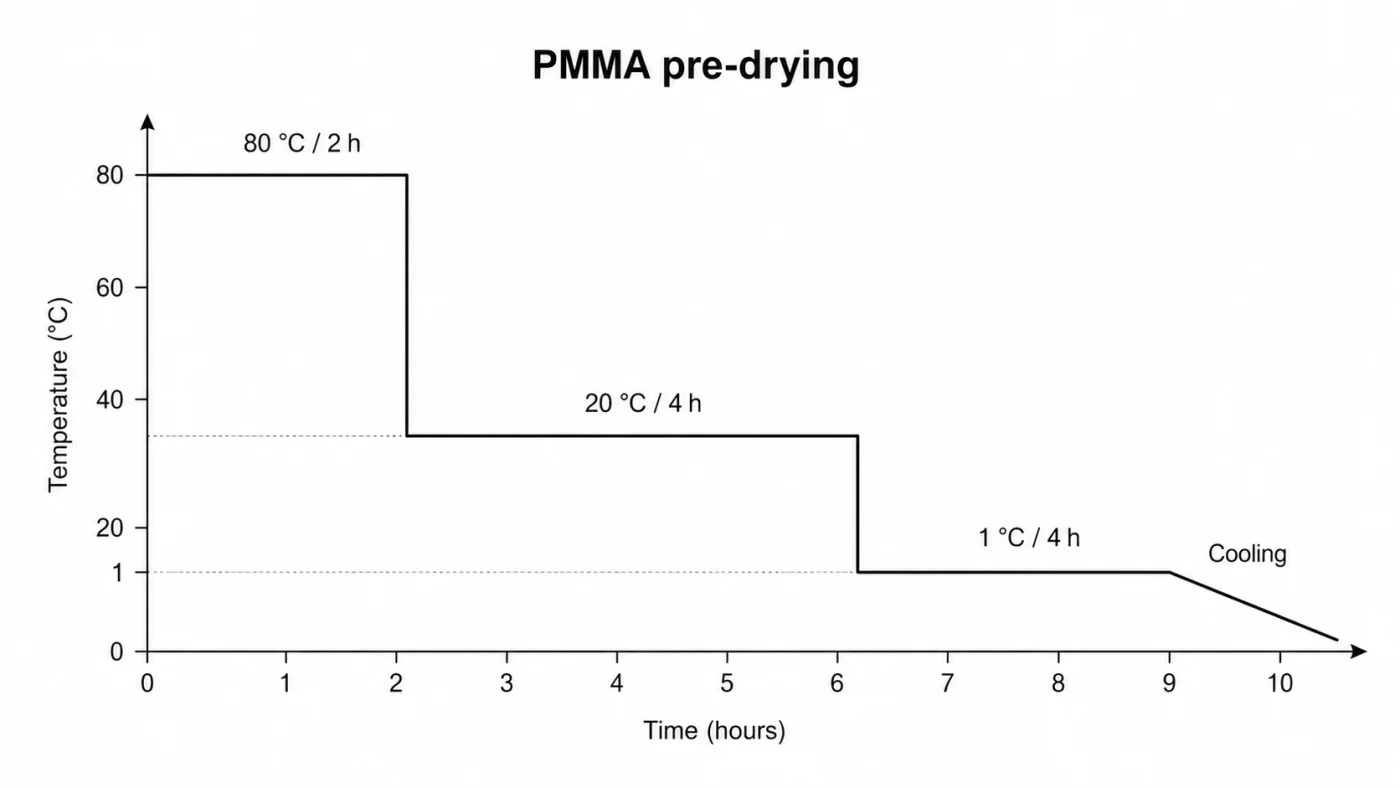
Material preparation is often more important than polishing. A stable PMMA process starts before the blank reaches the CNC machine.
- Stock selection: choose cast optical-grade PMMA when transparency and lower baseline stress are required.
- Moisture control: apply a controlled drying cycle based on the material supplier’s recommendations.
- Blank stress relief: use low-temperature conditioning for thick blanks or stress-sensitive geometries.
- Stabilization period: allow dried blanks to return to a controlled workshop environment before precision machining.
Optimized CNC Cutting Parameters for High-Clarity PMMA Valve Channels
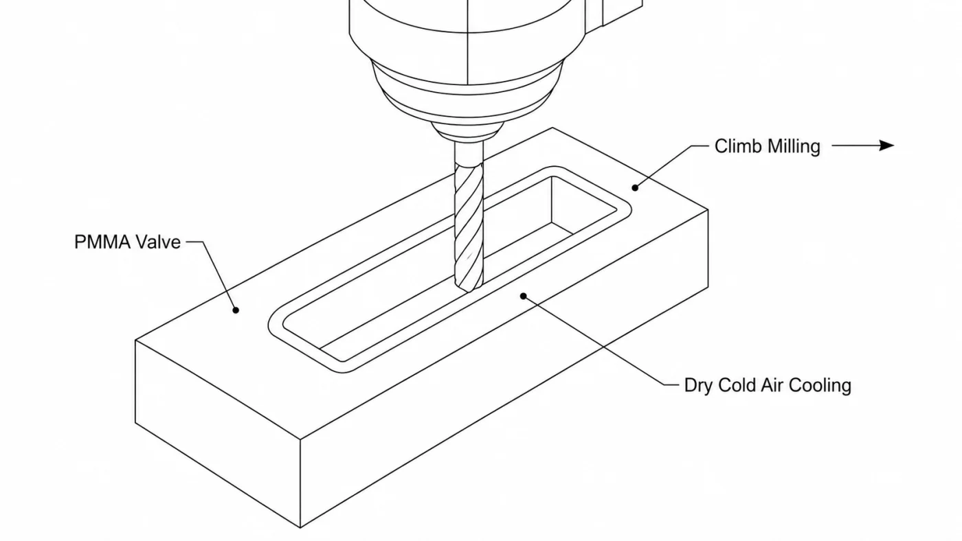
Exact parameters must be validated by part geometry, wall thickness, machine condition, cutter diameter, and PMMA grade. The following principles are commonly reviewed for transparent valve components:
- Cutter: polished single-flute solid carbide end mill for optical plastics.
- Cooling: clean dry air for chip evacuation and heat control.
- Strategy: separate roughing, semi-finishing, and finishing passes.
- Finish pass: use light engagement on transparent exterior and sealing surfaces.
- Inspection: verify sealing faces, bores, threads, and flow-channel geometry after machining.
Post-Processing Polishing and Annealing for Optical Transparency
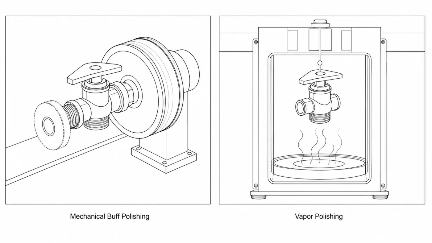
Mechanical Buff Polishing
Mechanical polishing is suitable for general laboratory parts and non-critical observation windows. It can improve visible clarity, but it must be controlled to avoid rounding sealing edges or changing critical dimensions.
Vapor Polishing
Vapor polishing may be used for higher-clarity transparent components where micro-scratches must be reduced. It should be evaluated carefully because surface chemistry, dimensional control, and stress relief all affect final part performance.
DFM Design Tips to Reduce PMMA Machining Risk
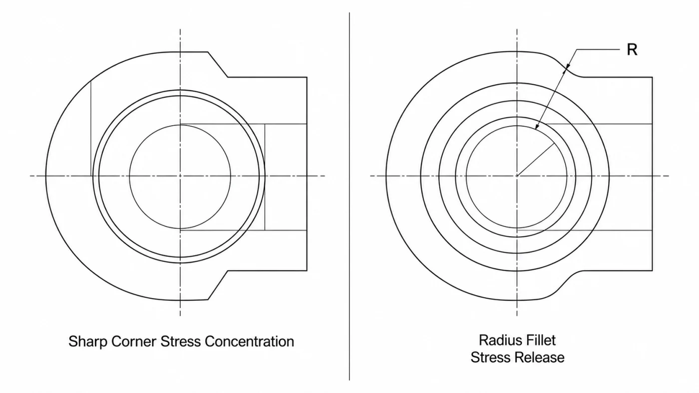
- Maintain enough wall thickness around transparent flow partitions to reduce warping.
- Add radius fillets to internal sharp corners where sealing function allows.
- Consider split-body valve construction for deep, narrow, or enclosed channels.
- Avoid thin protruding sealing tabs when raised gasket platforms are possible.
- Reserve tight tolerances for sealing interfaces and relax non-contact visual surfaces where possible.
PMMA vs PC for Transparent Valves
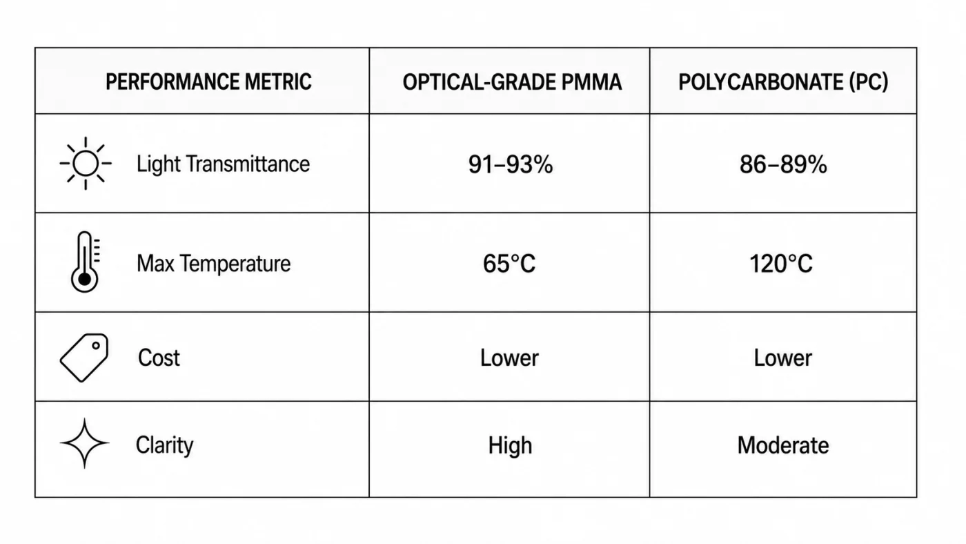
| Performance Metric | Optical-Grade PMMA | Polycarbonate (PC) |
|---|---|---|
| Light transmittance | Typically high, often around 91-93% | Typically lower, often around 86-89% |
| Machining tolerance | Good for transparent precision parts after stress control | Good toughness, but polishing behavior differs |
| Temperature resistance | Suitable for many room-temperature lab systems | Better for higher temperature service |
| Chemical exposure | Must be reviewed for alcohols and detergents | Often stronger impact resistance; chemical compatibility still needs review |
| Best fit | Transparent valve bodies, flow observation, polished PMMA parts | Impact-resistant transparent covers and higher-temperature transparent components |
FAQ for Engineers Sourcing Custom CNC PMMA Valve Components
Can PMMA valve sealing surfaces hold very tight tolerance?
Critical flat sealing areas can be machined and inspected tightly, but realistic tolerance depends on part size, wall thickness, geometry, polishing, and stress relief. For many transparent PMMA valve components, ±0.01 mm to ±0.05 mm is a more practical engineering discussion range than a single universal value.
Do you support prototype quantities?
Yes. Prototype and small-batch machining are suitable for fit, sealing, clarity, and fluid-path verification before production.
Does annealing extend lead time?
Yes. Drying, stress relief, polishing, and inspection can add process time, but they reduce the risk of delayed cracking, cloudiness, and sealing failure.
Can you review my STEP or PDF drawing before quotation?
Yes. Micrylix reviews material selection, wall thickness, channel geometry, sealing faces, tolerance requirements, and manufacturability before quotation.
Need Custom Transparent PMMA Valve Components?
Send your STEP, PDF, DWG, or sample photos for engineering review. We will review material suitability, machining risk, sealing requirements, optical clarity, and inspection needs before quotation.
Request RFQ