
CASE STUDY | PMMA CNC MACHINING
Custom PMMA Twin-Bore Flow Chamber
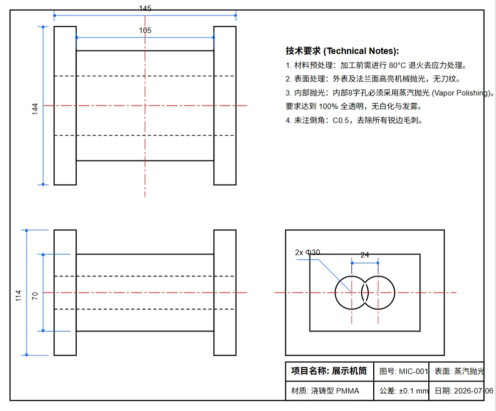
An anonymized drawing-based case study for a transparent cast PMMA chamber with two intersecting Ø30 mm bores, high-gloss exterior surfaces, and vapor-polished internal flow paths.
PROJECT SNAPSHOT
What Made This PMMA Part Difficult
On paper, this chamber looks simple: a rectangular transparent PMMA body with two large bores. In practice, the challenge is keeping the internal bore clear after CNC machining, polishing the outside faces without scratches, and avoiding stress whitening around machined edges.
CUSTOMER REQUIREMENT
Clear Internal Flow Paths Without Whitening
The customer needed a transparent flow chamber for an analytical or display-related fluid path. The internal twin-bore had to remain visually clear after machining and finishing. External faces and end faces required high-gloss mechanical polishing with no visible scratches.
The drawing also called out C0.5 chamfering on unmarked sharp edges, which matters on PMMA because small burrs and sharp corners can become crack-initiation points during assembly or cleaning.
Risks We Reviewed Before Machining
- Internal haze from heat buildup or chip recutting in the bores.
- Stress whitening around flange corners and machined edges.
- Uneven hand polishing inside the intersecting bore profile.
- Dimensional movement if raw cast PMMA stress is not relieved first.
MANUFACTURING APPROACH
Process Used for Optical PMMA Stability
Drawing and Material Review
We treated the part as an optical PMMA component, not a general plastic block. Cast PMMA was selected for better clarity and more stable machining behavior than extruded acrylic.
Stress-Relief Annealing
The drawing specifies 80°C pre-treatment. Holding and cooling time should be set according to stock thickness and supplier recommendation, rather than rushed as a short bake.
CNC Machining with Heat Control
Sharp polished cutters, controlled finishing allowance, and strong chip evacuation help reduce rubbing, heat marks, and cloudy surfaces inside the PMMA bores.
Mechanical and Vapor Polishing
External surfaces were mechanically polished. The internal twin-bore was handled with controlled vapor polishing because manual polishing cannot reach the intersecting internal profile evenly.
INSPECTION FOCUS
What We Checked Before Shipment
Inspection focused on the features that affect both appearance and function: bore diameter, bore position, overall envelope dimensions, chamfered edges, visible scratches, haze, whitening, and burrs around the openings.
For transparent PMMA parts like this, visual inspection is not a cosmetic extra. It is part of the functional check because cloudy flow paths can affect observation, lighting, or sensor performance in the final assembly.
Engineering Result
The finalized route gave the customer a repeatable manufacturing process for clear PMMA chambers without relying on hand work inside the bore. The key was not one “special trick”; it was stress control, clean cutting, correct polishing sequence, and careful edge finishing.
RELATED PAGES
Related PMMA and Optical Machining Resources
RFQ
Have a Similar Transparent PMMA Flow Part?
Send your drawing, material requirement, tolerance needs, finish requirement, and application notes. We will review machining feasibility, polishing risk, and material suitability before quotation.
STEP / PDF / DWG accepted · NDA available · Prototype and small-batch support